State-Space Method for Systems with Dashpot Damping

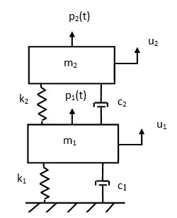
two_dof_system_dashpots

Structural dynamics systems can be represented in terms of mass, damping and stiffness matrices.  Each of these matrices may be coupled depending on the model complexity, degrees-of-freedom, etc.   The mass and stiffness matrices in the assembled equation of motion may be uncoupled using the normal modes for the undamped system.  This approach gives real natural frequencies and real mode shapes.

Damping effects can be included in forced response analyses by implicitly assuming that the damping matrix can be diagonalized into modal damping coefficients by the undamped modes.   But systems with dashpots in general have damping matrices which cannot be uncoupled in this manner.

The state-space method is useful for modal and forced response analysis of systems with discrete dashpot damping.  This approach yields complex natural frequencies and mode shapes, with real and imaginary components.

Here is a paper:

Two-Degree-of-Freedom System, State-Space Method:   two_dof_state_space_revE.pdf

More later…

– Tom Irvine

Honeycomb Sandwich Panels

Honeycomb-Sandwich-Panels-Marketimg_20171107_170159_750x750

Honeycomb sandwich structures are designed to have a high stiffness-to-mass ratio.   The stiff, strong face sheets carry the bending loads, while the core resists shear loads.

The face sheets are typically made from aluminum or carbon fiber with epoxy resin.

The honeycomb core material is usually aluminum for aerospace applications.   Other core materials include Nomex aramid or Kevlar para-aramid fiber sheets saturated with a phenolic resin.  In addition, closed cell foams such as Rohacell are substituted for honeycomb in some sandwich panel designs.

* * * *

According to Klos, Robinson and Buehrle…

Panels constructed from face sheets laminated to a honeycomb core are being incorporated into the design of modern aircraft fuselage and trim treatments. The mechanical properties of these panels offer a distinct advantage in weight over other commonly used construction materials.

The strength to weight ratio of honeycomb composite panels is high in comparison to rib stiffened aluminum panels used in previous generations of aircraft. However, the high stiffness and low weight can result in supersonic wave propagation at relatively low frequencies, which adversely affects the acoustical performance at these frequencies.

Poor acoustical performance of these types of structures can increase the cabin noise levels to which the passengers and crew are exposed.

* * * *

Honeycomb sandwich structures are used in a wide variety of critical structures in Air
Force space systems. These include payload fairings (shrouds) for launch vehicles, adapters for mounting of satellite payloads, solar array substrates, antennas, and equipment platforms.

Since 1964, there have been several known or suspected failures of honeycomb structures. These failures have been attributed to the lack of venting in the panel design manufacture. On the other hand, based on available information, vented honeycomb sandwich panels never have experienced failure during flight. In the cases documented herein, the consequences of the failures have been significant and costly.

Honeycomb sandwich panels that are not vented will contain air (and possibly volatiles,
including moisture) which causes a pressure differential during launch into orbit. If heating also is involved, the internal pressure will rise further. In any case, each individual unvented honeycomb cell acts as a tiny pressure vessel imposing stresses on the skin-to-core bonds. If these stresses are high enough, panel failure (i.e., skin-to-core debonding) will occur. Certain defects introduced during panel manufacture would make failure more likely.

Excerpt from:  SMC-TR-94-02

* * * *

Constrained layer damping material consists of a viscoelastic material on the bottom and a stiff constraining layer on top

It uses shear deformation in the viscoelastic layer for energy dissipation

The use of “add-on” constrained layer damping may be difficult to achieve for composite and sandwich-composite structures due to the high stiffness of the base structure. Better damping is achieved by embedding the viscoelastic material either in the skin or in the core.

Reference:  Hambric, Sung, Nefske, Engineering Vibroacoustic Analysis, Wiley, West Sussex, United Kingdom, 2016

* * * *

Here are some references:

Natural Frequencies of a Honeycomb Sandwich Plate:  honeyG.pdf

Honeycomb Sandwich Panel Damping:  honeycomb_sandwich_damping.pdf

Honeycomb Sandwich Ring Mode Frequency:  honeycomb_sandwich_ring_frequency.pdf

Hexcel Honeycomb Sandwich technical information:  honeycomb_design.pdf

Sound Transmission through a Curved Honeycomb Composite Panel:  ST_curved_honeycomb_panel.pdf

More later…

– Tom Irvine
Extract Mass & Stiffness Matrices from Nastran model

The punch file method may be used to extract the mass & stiffness matrices from Nastran models.  The format is awkward since zero terms are not stored.  Also the matrices are assumed to be symmetric, and the upper triangular portion above the diagonal is not stored.

Here is a paper from the Middle East Technical University which explains the format:  paper link.

The key is to apply the following command in the *.nas, *.dat, *.bdf or equivalent file:

PARAM,EXTOUT,DMIGPCH

Here is a sample file for a fixed-free beam, aluminum, 24 inch long, solid cylinder, 0.25 inch diameter, 24 elements:  beam_24e_diam_0p25_punch-000.nas

Its punch file output is:  beam_24e_diam_0p25_punch-000.pch

The fundamental frequency is 11.9 Hz.

If Femap is used, select the punch output with coupled mass.

Here is a C++ program which converts the punch file into full mass & stiffness matrices in ASCII text format:

mass_stiffness_punch.cpp

mass_stiffness_punch.exe

The mass & stiffness matrices can then be imported to Excel, Matlab or some other program.

* * *

Note:  the dimension of the extracted mass matrix will be less than that of the stiffness matrix for models with massless nodes.

Here is a workaround:

An Indirect Method for Extracting Nastran Full Mass Matrices for Models with Massless Nodes  extract_massless_node.pdf

– Tom Irvine

Mode Acceleration and Inertia Relief for a Semi-definite Structural Dynamics System

NASAsoundingrocket

Aircraft and launch vehicles behave as unconstrained systems in flight, with six rigid-body modes. These vehicles may be “trimmed” using aerodynamic control surfaces and thrust vector control to prevent rotation about the vehicle center-of-gravity (CG).

There is a need to calculate the vehicle’s displacement response to wind, gusts, buffeting and other external forces. This process requires separating the rigid-body response from the elastic response. The elastic response is the relative displacement referenced to the CG displacement. The stress and strain can then be calculated from the elastic displacement response. The method is carried out by inertia relief, where rigid-body motion is constrained by applying an inertial acceleration that is opposite to the acceleration resulting from the external forces.

Here is a paper, which is a work-in-progress inertia_relief.pdf

See also:  The Mode Acceleration Method  MA_method.pdf

Mode Acceleration Method Matlab scripts

mdof_modal_arbit_force_newmark_MA.m (main script)
Generalized_Eigen.m
mdof_plot.m
ODE_force_input.m
Newmark_modal_force_MA.m
line_colors.m

– Tom Irvine

Modal Test Problem & Solution

Ideally, a modal test on a structure would be performed with completely free boundary conditions.  This configuration can be approximated by mounting the structure on compliant air cushions, or by suspending it with elastic cords, so that the mounted natural frequency is much smaller that the structure’s fundamental frequency.

Other choices would be to test the structure with one boundary fixed, or in its final installation configuration.

But there may be certain cases where a structure can only be tested at its “next higher level of assembly.”  NASA is facing this issue for a launch vehicle which can only be tested on its launch platform and tower assembly due to cost and schedule reasons.

The modal test results will thus be for the complete system rather than the vehicle by itself.  But the need is for the vehicle’s modal parameters, which can then be used to calibrate the stiffness in a finite element model.  This would be for the case immediately after liftoff when the vehicle boundary conditions are free-free.  The vehicle natural frequencies and mode shapes are needed to check control stability, structural stresses, etc.

Here is paper which offers a potential solution by extracting the subsystem stiffness matrix from system level modal test results with a known mass matrix.  A simple three-degree-of-freedom system is used.  The parameters are conceptual only and do not represent those of the launch vehicle and its platform.

Note the reduction method in this paper may be similar to System Equivalent Reduction Expansion Process (SEREP) which is used in the automotive industry.

See also:

Receptance Decoupling for Two Rigidly Connected Subsystems

Determination of the Fixed-Base Natural Frequencies for a Two-degree-of-freedom System via Modal Test Receptance

– Tom Irvine

Transverse Vibration of a Rotating Beam via the Finite Element Method

rotating_beam

A function for calculating the natural frequencies and mode shapes for an elastic beam undergoing rotation is given in:

Matlab script: Vibrationdata Signal Analysis Package

The function can be accessed via:

>> vibrationdata > Miscellaneous > Structural Dynamics > Beam Bending > Rotating Beam, FEA

An option is included for calculating the response to a uniform force/length.

* * *

See also:  Beam_FEM_rotating.pdf

– Tom Irvine

Beam Supported by End Springs

beam_springs
A function for calculating the natural frequencies and mode shapes for an elastic beam supported by end springs is included in:

Matlab script: Vibrationdata Signal Analysis Package

The function can be accessed via:

>> vibrationdata > Miscellaneous > Structural Dynamics > Beam Bending > Beam with End Springs, FEA

Options for calculating the beam response to an applied force will be added soon.

* * *

See also:  Beam Bending Finite Element Analysis

– Tom Irvine

SDOF System Response to Initial Velocity & Displacement

Mass_spring

I have added a function for calculating the free vibration response of an SDOF system to initial conditions to the Vibrationdata GUI package.

Matlab script: Vibrationdata Signal Analysis Package

>> vibrationdata  > Miscellaneous > Structural Dynamics > Spring-Mass Systems > SDOF Free Vibration Response to Initial Conditions

* * *

Reference: free.pdf

* * *

– Tom Irvine

Cylindrical Shell Natural Frequencies & Mode Shapes

A function for calculating cylindrical shell natural frequencies via the wave method is now included in the Vibrationdata GUI package.

Matlab script: Vibrationdata Signal Analysis Package

This function may be accessed via:
vibrationdata > Structural Dynamics > Rings & Cylinders > Cylinder, Wave Model

Reference Papers

Study on applicability of modal analysis of thin finite length
cylindrical shells using wave propagation approach:  Link

Natural Frequencies of a Finite, Thin-Walled Cylindrical Shell: cylindrical_shell.pdf

– Tom Irvine

Rectangular Plate Bending Frequencies and Mode Shapes, Finite Element Method, GUI version

mm1

I have added a feature for rectangular plate bending modes to the Matlab GUI package.

Matlab script: Vibrationdata Signal Analysis Package

The script allows for the addition of point masses and point constraints.  This is a work-in-progress.  The next step will be to add base excitation options.

The new feature can be accessed via:

vibrationdata > Miscellaneous > Structural Dynamics > Plates, Rectangular & Circular > Rectangular Plate, Finite Element Method

* * *

Here is a reference paper: FEA_plate_bending.pdf

See also:  Dynamic Response to Enforced Motion

* * *

– Tom Irvine