Turbine Engine Blade-off Test

Rolls Royce Engine Blade-off Test     Video Link 1     Video Link 2

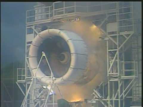
The engine blade-off test is performed to make sure that the engine can survive a fan. compressor or turbine blade breaking off within the engine, without fragments being ejected through the outside enclosure of the engine.  This is a containment requirement.

A fan blade is deliberately detached during the test using an explosive device while the engine is running at maximum thrust. The test does not require that the engine continues to operate after the blade failure.

The resulting blade loss causes a rotating imbalance force which can induce moderate to severe structural vibration.

For an actual flight occurrence, the engine would be shut down. There is no means of stopping the engine from continuing to rotate while there is sufficient airflow through the fan section to drive the engine. So it would continue to “windmill” without producing any thrust. The rotating imbalance vibration would persist under these conditions.

* * * * *

Here is a related video on the topic of fan blade loss…

Dr. David Ewins presentation excerpt

See: Exciting Vibrations: The Role of Testing in an Era of Supercomputers and Uncertainties

Go to 27:00 minute mark and watch for about six minutes

* * * * *

Fatigue accounts for a significant number of turbine and compressor blade failures and is promoted by repeated application of fluctuating stresses. Stress levels are typically much lower than the tensile stress of the material. Common causes of vibration in compressor blades include stator passing frequency wakes, rotating stall, surge, choke, inlet distortion, and blade flutter. In the turbine section, airfoils have to function not only in a severe vibratory environment, but also under hostile conditions of high temperature, corrosion, creep, and thermomechanical fatigue.   Reference

* * * * *

Flight Case Histories

AirAsia X Flight D7237, Airbus 330, Royce-Rolls Engines June 25, 2017
Video Link 1     Video Link 2

* * * * *

Southwest B737 near Pensacola on Aug 27th 2016, Uncontained Engine Failure
Report Link

Engine damage seen on the ground (Photo: Peter Lemme)

* * * * *

Thomas Cook Airline, Airbus A330, Rolls Royce Engines, Turbine Blade Fails
Manchester Airport UK, Monday 24 June 2013.   Video Link   Report Link

The blade failure was caused by high cycle fatigue (HCF) crack propagation with crack initiation resulting from ‘Type 2 sulphidation’ corrosion.

* * * * *

Qantas Boeing 747-400 near Singapore on May 9th 2011, Fatigue Fracture of Blade 24

The fatigue fracture of blade 24 (Photo: ATSB)

Article Link

The engine was removed and sent for further analysis. Disassembly revealed only minor damage to internal components. The root of the fractured blade was removed and sent for laboratory analysis. The analysis revealed the blade had fractured as result of growth of a low stress/high cycle fatigue crack.

See also:  AC 25-24 – Sustained Engine Imbalance

– Tom Irvine

Embraer E190 Landing Shock

EMBRAER_E190_(8373095236).jpg

e190

I recently flew as a passenger on a E190 similar to the one in the top image. The landing shock is shown in the bottom image. The data was recorded on a Slam Stick X, sampled at 400 samples/sec. The initial set of peaks have a frequency of about 0.9 Hz.

Matlab File: E190_landing_shock.mat

See also: Landing Shock

– Tom Irvine

A330-200 Landing Shock

a330_200

Image Courtesy of Justin Kane

I recently flew as a passenger on a A330-200 similar to the one in the image.  I used a Slam Stick X Vibration Data Logger to measure the landing shock, with the sensor mounted on the cabin floor.  The acceleration time histories for two axes are shown in the following figures.

a330_200_landing_fore_aft

a330_200_landing_vertical

The vertical axis response has several spectra between 0.5 and 2.0 Hz.

A330-200 Landing Shock Matlab file

See also:  Landing Shock

– Tom Irvine

A320 Landing Shock

a320_jb

I recently flew as a passenger on a A320 similar to the one in the image.  I used a Slam Stick X Vibration Data Logger to measure the landing shock, with the sensor mounted on the cabin floor.  The resulting acceleration time history is shown in the following two figures, longer and shorter views.  The main wheels touch down at the zero second mark. The nose wheels contact the runway about 3.5 seconds later.

logan1

logan2

The higher frequency energy between zero and 0.5 seconds consists of components in the 10 to 15 Hz frequency domain, likely representing structural modes.  The sample rate was 400 samples per second.

A320 Landing Shock Matlab file

See also: Landing Shock

– Tom Irvine

Jet Aircraft EPNL

aircraft_noise_sources_mod-520x245

There are several tools for analyzing jet aircraft sound as measured on the ground.    The measurements would typically be made for takeoff and final approach at or near an airport.  Fly-over sound levels can also be recorded.

The tools begin with the unweighted, one-third octave sound pressure level (SPL).  One SPL should be taken for each 0.5 second increment.  Furthermore, each SPL should have an overall sound pressure level that is within 10 dB of the maximum overall level.

The tools build upon one another in this order:

  1.  Sound Pressure Level (SPL)
  2.  Perceived Noisiness (Noys)
  3.  Perceived Noise Level (PNL)
  4.  Tone Corrected Perceived Noise Level (PNLT)
  5.  Effective Perceived Noise Level (EPNL)

Each of the functions is in units of dB except for Noys. The Effective Perceived Noise Level is sometimes represented as EPNdB to emphasize that it is a decibel scale.   The functions are defined in Annex 16 of the ICAO International Convention on Civil Aviation, and in the US Federal Air Regulations Part 36.

Noy is a subjective unit of noisiness. A sound of 2 noys is twice as noisy as a sound of 1 noy and half as noisy as a sound of 4 noys.

The Matlab scripts for the EPNL processing are included in the GUI package at: Vibrationdata Matlab Signal Analysis Package

The function can accessed via:

>> vibrationdata > Select Input Data Domain > Sound Pressure Level

An alternative is to compute the A-weighted SPL.  This option is also available in the Matlab GUI package.  Nevertheless, the EPNL is used by convention for jet aircraft noise.

– Tom Irvine

Aircraft Auxiliary Power Unit (APU)

apu

GTCP85-98D APU

The APU is a small gas turbine engine which is normally located in the tail cone of the aircraft but, in some cases, is located in an engine nacelle or in the wheel well. The APU can be started utilizing only the aircraft batteries and, once running, will provide electrical power to aircraft systems as well as bleed air for air conditioning and for engine start. Aircraft APUs generally produce 115 V alternating current (AC) at 400 Hz (rather than 50/60 Hz in mains supply), to run the electrical systems of the aircrat.

apu_fft

The sound track from an engine test was extracted from: YouTube video

A Fourier transform was applied to the sound time history. The Y-axis is unscaled sound pressure. The steady-state portion yielded a spectral line near 700 Hz which corresponds to the rotor speed of 42,000 RPM, Harmonics are also present at 3X & 6X.

– Tom Irvine

Boeing 717-200

1024px-AirtranJet

I recently flew as a passenger on a Boeing 717-200 aircraft similar to the one shown in the image.  This aircraft has two Rolls-Royce BR700 engines, with the following specifications:

Maximum Engine Rotational Speeds (Both Engines)

N1 Low Pressure Turbine = 6,195 RPM (103 Hz)
N2 High Pressure Turbine = 15,898 RPM (265 Hz)

I made an audio recording from inside the cabin during take-off and climb-out.

data_plot

The sound file Fourier transform for a 10-second segment is shown in the image.

The first peak is at 88 Hz, which is 85% of the maximum N1 speed.

The second peak is at 129 Hz and is unidentified.

Most of the higher frequency peaks are integer multiples of 88 Hz.

Complete audio file:  Boeing_717_200.mp3

The Fourier transform was taken from 40 to 50 seconds into the recording.

A “buzz saw” sound occurs due to shock waves at the turbofan blade tips which have a supersonic tangential velocity.

– Tom Irvine

Embraer ERJ 145 Acoustics

emb145

Figure 1.  ERJ (EMB) 145 Aircraft

Rolls-Royce_AE_3007_2

Figure 2.  Rolls-Royce AE 3007 Series Turbofan Engine

emb145_fft

Figure 3.  Fourier Magnitude, ERJ 145 Climb-out

I recently flew as a passenger in an EMB 145 jet similar to the one shown in Figure 1.

This aircraft has two Rolls-Royce AE 3007 series turbofan engines turbofan engines, as shown in Figure 2.

Here are the rotational speeds for each rotor.

Fan Speed                       7903 RPM   (132 Hz)
Gas Generator Speed   16013 RPM   (267 Hz)

Note that there are several variants of this engine with slightly different rotor speeds.

I made an audio recording from within the aircraft cabin during climb-out, while hearing some distinct sine tones against the background random noise. The audio file is: emb145.wav

A Fourier transform of the sound file is shown in Figure 3.  Spectral peaks occur at 133 and 267 Hz, which agree with the specifications for the engines.

Again, this recording was made from inside the cabin. So the fuselage walls would have attenuated some of the engine-generated acoustic energy, particularly at higher frequencies.

* * *

– Tom Irvine